Sign In | Join Free | My himfr.com |
|
Ask Lasest Price | |
Brand Name : | GSKA |
Model Number : | Genset Diesel Generator |
Price : | Negotiable |
Payment Terms : | T/T L/C, 30% deposit,70% before delivery |
Supply Ability : | 100 units/ Per month |
Delivery Time : | 30 days |
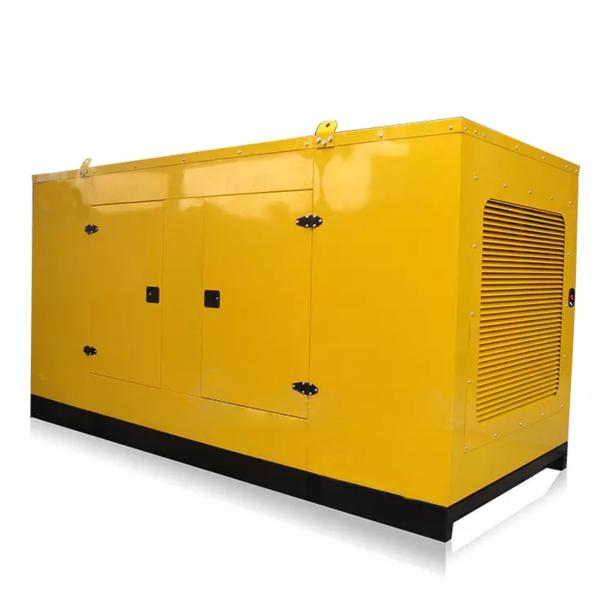
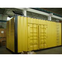
50/100/500KW Convenient Silent Diesel Generator Set 120V/400V
Coordinated control of battery energy storage and diesel generator in independent AC microgrid
In the independent AC microgrid system, the coordination control
between the diesel generator and the battery energy storage is the
key to ensure the stable operation of the system. Based on the fast
response characteristic of battery energy storage, a coordinated
control method of diesel generator and energy storage battery was
proposed. When the diesel generator is used as the main power
supply, the auxiliary power control signal is introduced into the
traditional droop control of the energy storage system to prevent
the system collapse caused by the diesel engine overcurrent for a
long time and improve the system stability. Aiming at the
short-time power outage problem when the main power supply in the
microgrid changes from the energy storage system to the diesel
generator or from the diesel generator to the energy storage
system, a seamless switching control strategy of the two main power
supplies of the diesel generator and the energy storage battery is
proposed.
Modeling and operation simulation of Marine Diesel generator Set
The operation process of Marine diesel generator set is an
important part of power plant operation. The number of diesel
generators operating in parallel determines the capacity of a
Marine power station. The stability of parallel operation is
closely related to the stability of Marine power station. It is of
great significance to establish a mathematical model which can
accurately reflect the operation of diesel generator set for
operation control, simulation and performance analysis of power
station. The study of parallel operation of diesel generator sets
involves the establishment of diesel generator model, parallel
operation control model and electric load model. Although there are
some different modeling methods for diesel generator model, most of
them are limited to single model simulation. Taking diesel
generator model as the core, the mathematical model of parallel
operation of multiple diesel generator sets is established. Taking
the "Yu-kun" ship power station as the reference object, the diesel
generator model, power load model and parallel operation control
system model are established respectively
The basic structure:
The basic structure of diesel generator is composed of diesel
engine and generator. The diesel engine drives the generator to
generate electricity.
The basic structure of diesel engine: cylinder, piston, cylinder
head, inlet valve, exhaust valve, piston pin, connecting rod,
crankshaft, bearing and flywheel components. Diesel generator
diesel engine is generally single cylinder or multi cylinder four
stroke diesel engine, I just talk about the basic principle of the
work of single cylinder four stroke diesel engine: diesel engine
starting is through manpower or other power to rotate the diesel
crankshaft so that the piston in the top closed cylinder for up and
down reciproCAT-parts-partsing motion. The piston completes four
strokes in motion: the intake stroke, the compression stroke, the
combustion and work (expansion) stroke and the exhaust stroke. When
the piston moves from up to down, the inlet valve opens, and the
fresh air filtered by the air filter enters the cylinder to
complete the intake stroke. The piston moves upward from the
bottom, the inlet and exhaust doors are closed, the air is
compressed, the temperature and pressure increase, complete the
compression process. When THE piston is about to reach the top, THE
fuel INJECTOR will spray the filtered fuel into the combustion
chamber in a mist and mix with the air of high temperature and
pressure to burn on its own immediately. The high pressure will
push the piston down to work, push the crankshaft to rotate and
complete the work stroke. After the work stroke is finished, the
piston moves up from the bottom, and the exhaust valve opens the
exhaust to complete the exhaust stroke. The crankshaft rotates half
a turn for each stroke. After several working cycles, the diesel
engine gradually accelerates to work under the inertia of the
flywheel.
Engine Data:
Manufacturer / Model: | DCEC Cummins 6CTA8.3-G2, 4-cycle |
Air Intake System: | Turbo, Water/Air Cooling |
Fuel System: | PB/W type fuel pump |
Cylinder Arrangement: | 6 in line |
Displacement: | 8.3L |
Bore and Stroke: | 114*135(mm) |
Compression Ratio: | 17:1 |
Rated RPM: | 1500rpm |
Max. Standby Power at Rated RPM: | 180KW/244HP |
Governor Type: | Electronic |
Exhaust System | |
Exhaust Gas Flow: | 34.7m3/min |
Exhaust Temperature: | 570℃ |
Max Back Pressure: | 10kPa |
Air Intake System | |
Max Intake Restriction: | 6kPa |
Burning Capacity: | 12.4m3/min |
Air Flow: | 238m3/min |
Fuel System | |
100%( Prime Power) Load: | 215 g/Kw.h |
75%(Prime Power) Load: | 211 g/Kw.h |
50%(Prime Power) Load:: | 216 g/Kw.h |
100%( Prime Power) Load: | 39.7L /h |
Oil System | |
Total Oil Capacity: | 23.8L |
Oil Consumption: | ≤4g/kwh |
Engine Oil Tank Capacity: | 18.9L |
Oil Pressure at Rated RPM: | 276-414kPa |
Cooling System | |
Total Coolant Capacity: | 34L |
Thermostat: | 82-95℃ |
Max Water Temperature: | 104℃ |
Alternator Data | |
Number of Phase: | 3 |
Connecting Type: | 3 Phase and 4 Wires, “Y” type connecting |
Number of Bearing: | 1 |
Power Factor: | 0.8 |
Protection Grade: | IP23 |
Altitude: | ≤1000m |
Exciter Type: | Brushless, self-exciting |
Insulation Class, Temperature Rise: | H/H |
Telephone Influence Factor (TIF): | <50 |
THF: | <2% |
Voltage Regulation, Steady State: | ≤±1% |
Alternator Capacity: | 182KVA |
Alternator Efficiencies: | 92.4% |
Air Cooling Flow: | 0.514m3/s |
![]() |